Center Yourself
A perhaps under-discussed element of line array design and deployment is the center of gravity (COG) of the array in relationship to the flybar. Most prediction software platforms will indicate the COG to the user. If you are flying the array with a single pick point, the shackle must be directly above the COG in order for the array to have the intended vertical inclination.
Put a different way, whenever an object is suspended from a single point, it will always orient itself such that the COG of the object is directly below the pick point (See Entertainment Rigging by Harry Donovan for a deep exploration of this idea and its ramifications). If we pick in front of the COG, the entire array will tilt upwards. If we pick behind the COG, the entire array will tilt downwards.
In Figure 1 below, the desired vertical aiming of the array is 0°, with the flybar perfectly horizontal. The blue line indicates that the COG falls directly between two flybar pick points. If we are flying the array with a single pick, we must choose one or the other. The exact amount of error can be more depending on factors including the length and curvature of the array, weight distribution of the particular loudspeaker product, and the design of the rigging hardware.
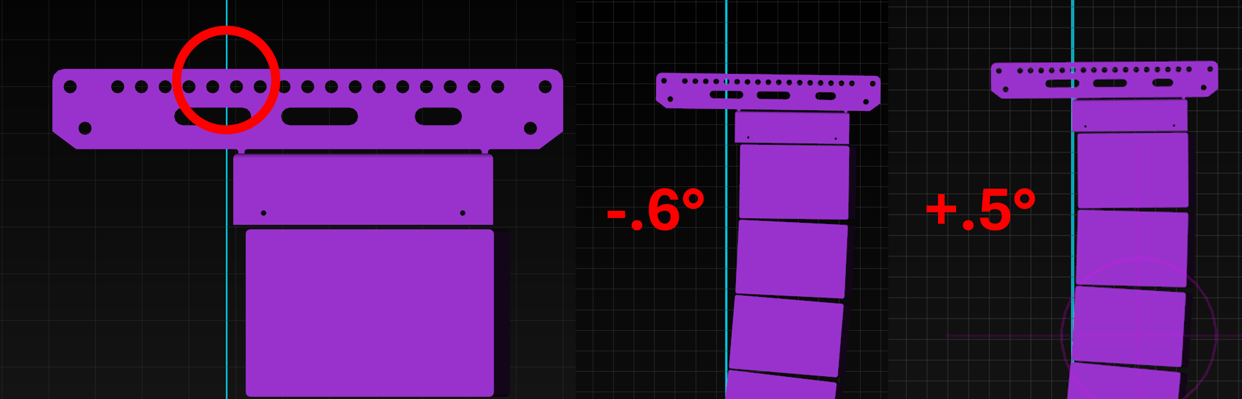
FIGURE 1 - Left: the COG falls between available shackle holes. Right: choosing the nearest holes results in an inclination error.
Is a half degree vertical aiming error significant? Probably not in most circumstances, but if you happen to have some 0.5° splays at the top of your array, you’re now off by an entire box, which we can plainly consider to be a significant error. For the purposes of this discussion, we are ignoring other sources of error including cable weight, which can also deflect vertical inclination with a single-point pick.
Hanging an array with two points - front and back of flybar - allows us to adjust the motors independently and therefore adjust the vertical inclination once the array is in the air. Note that proper inclination can only be determined once the array is at trim height, using a laser and/or inclinometer unit mounted to the flybar.
Some people try to set proper inclination when the array is floating at deck height, using a mechanical inclinometer or smartphone app pressed against the cabinet of the bottom box. This fails for a few reasons - one of which being that most line array cabinets are trapezoidal in profile, so the cut angle of the bottom cabinet is not the aiming angle of the bottom box on-axis center line in the prediction software which is used to calculate vertical coverage.
The bigger issue, however, is that chain hoists typically don’t run at the same speed, particularly when loaded unequally. If the desired inclination is set at deck height and then the array is taken to trim, the inclination has probably changed by the time the array gets to height. (Investigate this yourself by taking an inclo reading at deck height and then again at trim). With a typical two-point hang spaced by three feet, it takes less than a third of an inch of chain length difference to create the same half-degree error as above.
The Relativity of Wrong
Exactly how concerned should we be about these sub-1° inclination errors? Is it a tangible problem that we need to be vigilant about? Or is this yet another example of the Magnitude Fallacy - a real effect based in real science and math, but so small as to be negligible in real-world circumstances?
Let’s see if we can put some numbers to it. Figure 2 shows a 17-element large-format line array hung at a trim height of 40 feet - something that we might be reasonably likely to encounter at an outdoor festival stage or amphitheater, for example. I’ve set the entire array to 1° splays, and aimed it so that the second box impacts the ground at 300 ft from the array.
While hanging an array of all 1° angles is probably inadvisable in terms of coverage uniformity, we can measure the ground distance between two adjacent center line impacts to see how much error in coverage is created by a 1° error in array inclination.
The red scale across the bottom shows distance from the array, and the orange rectangles span the distance between two adjacent center line impacts at milestone distances of 50, 100, 150, 200, 250 and 300 feet from the PA. The grey background grid indicates 10’ increments.

FIGURE 2: Measuring the distance between adjacent 1° impact points (orange rectangles) allows us to evaluate the error in coverage caused by a 1° error in splay at various distances from the array.
Of course, these numbers will vary greatly depending on the trim height and audience geometry but this gives us a real feel for it: up close to the PA, the error is relatively small (6.5’ at a distance of 50 feet), while at a distance of 200 feet from the PA, a 1° inclination error moves our impact point by a substantial 29 feet, and we are approaching 40 linear feet of error at the 250’ mark. That’s about 12 rows of seats.
If our top box is supposed to cover to 300 feet, and we’re 1° too high on the inclination, it’s hitting at 362 feet, which is an error of 20% of the total coverage depth. Readers are encouraged to draw their own conclusions from this, but personally I wouldn’t consider this negligible, especially for systems throwing long distances and impacting audience geometry at shallow angles (that means the corresponding error also gets larger with lower trim heights).
So inclinometers really are important, and this is also a good argument for building a little extra vertical splay into your design so it’s a bit more robust against small aiming errors - particularly with single-point hangs, because we’re unable to adjust those once the array is deployed without landing the rig and adjusting the shackle pick point, and of course the prediction software doesn’t take into account the additional torque on the flybar caused by the cable loom hanging at the rear.
With a two point hang, we can of course bump our motors to accomplish the proper inclination - except when we can’t. Using two motors to tilt the flybar up or down redistributes the weight between the front and rear points as the array tilts and the COG shifts forwards and backwards. At the extremes, all the weight is concentrated on one point or the other, and we’re unable to tilt any further.
Note that this doesn’t just apply to cases of extreme uptilt and downtilt, but also to designs with a lot of curvature: the boxes at the bottom of the “J” pull the COG substantially towards the rear, such that it’s easy to end up with all the weight on the rear point even with the flybar at a flat angle.
Workarounds
So what do we do? Using an extension bar on the flybar gives us more distance between the two pick points and therefore allows a wide range of uptilt and downtilt, or more heavily curved array geometries, but in rare cases that still might not be quite enough - and sometimes we may not have an extension bar available. (In some cases we may have the ability to add a pullback rigging point for cases of extreme downtilt, but that also requires special hardware, and the number of circumstances in which we can do that is relatively low.)
If all the weight is landing at the rear point, trimming a bit lower means tilting the entire array upwards to have the top box hit at the same spot in the room, which shifts some of the weight forward, but the lower trim may not be an acceptable compromise in your particular situation. We can also play with line length. Cutting a few boxes and hanging a shorter line may bump the COG back underneath the flybar and yield a “riggable” design.
If neither of these solutions are appropriate, we can resort to a less conventional solution, which is a polite euphemism for “dirty tricks.” We can game the system by using array cabinets specifically to shift the COG of the array in a way that’s favorable to us by using them as a counterweight.
In the design shown on the left side of Figure 3, there were no extension bars available and the array frame is relatively shallow, which means we are at increased risk for COG challenges. We’re in a theater with a balcony, with a lot of listeners higher than the trim height of the array, which means significant uptilt on the flybar. With all 12 boxes at the proper curvature to cover from the back of the balcony to the front row, the COG would land in front of the flybar, not possible to hang. The solution shown is to increase curvature towards the bottom of the array such that the second to last box, rather than the last box, impacts at the desired start of coverage at the front row.
On the left side of Figure 3, Box 12 appears to be massively over-splayed and impacting the edge of the stage, but it’s not even plugged in; it’s just acting as a counterweight and pulling the COG back into a usable position underneath the flybar.

FIGURE 3 - Left: Box 12 is a disconnected counterweight box, intentionally over-splayed to control the COG.
Right: Box 17 is a counterweight box allowing the desired uptilt with the extension bar.
That, combined with attaching the cable loom directly to the rear of the flybar to add additional weight at the rear, allowed me to accomplish the desired uptilt and send energy into the rear of the balcony. (Line length enthusiasts can feel free to connect the box to amplification and simply mute the MF/HF, using it for LF extension.)
The right side of Figure 3 shows another more subtle variation of the same principle - although the bottom box was still required for coverage into the ADA area flanked by the blue chairs, it is splayed open further than strictly required for coverage purposes, and the extra curvature was enough to nudge the COG back under the front rigging point.
I have also used this the converse of this principle - counterweight boxes at the top of the array - to circumvent a sticky rigging situation in the past. In Figure 4, we are working with a single fixed rigging point that is only 22” from the rear wall, which limits our curvature. Aiming the top box as intended and curving the array to accomplish the desired coverage would result in a collision with the wall. So we must be creative.

FIGURE 4 - Counterweight boxes at the top of the array accomplish the needed uptilt while avoiding a structural collision.
The top two elements create far more overshoot than I needed in the design - the design proper actually starts at box 3 - but they serve to nudge the COG forward just enough to land under the proper flybar pickpoint and achieve the necessary uptilt on the frame while avoiding collision with the rear wall and leaving a few inches behind the bottom element for cable looms to pass through, and for safely de-rigging the system after the show.